3D Printed Springs - Part 1
A parametric study of the characteristic stiffness for 3D-printed springs
The Test Fixture
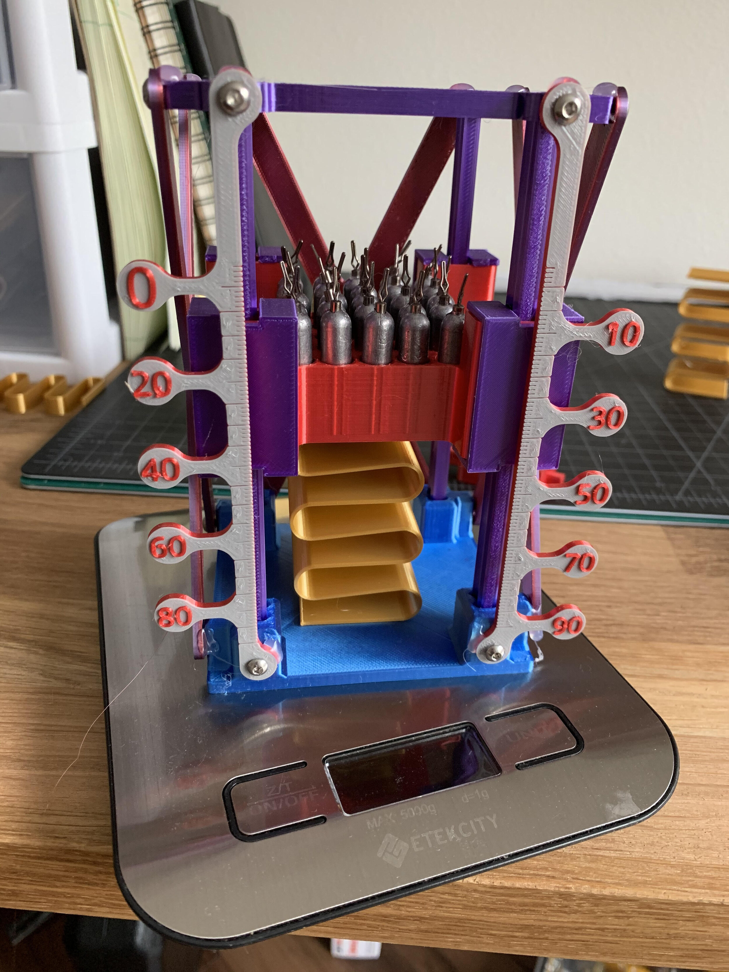
This project was originally motivated by the desire to have a model for the characteristic stiffness of a 3D-printed springs in order to be able to set the suspension properties on the RC Truck project. In order to do this experiment, a test fixture was needed - so that lead to some linear rail and bearing design fun over a few weeks and finally resulted in this
There are a few features which have been designed in, based on the iterations
Linear rails have indents for the bearings to ride in
The bearing carriers have a triangular design, no bearing cage/spacers, and a small lash designed in
The baseplate accepts the linear rails and the cross-bracing keeps everything rigid
The scale is built-in to the frame as well, which makes reading the spring displacement easier
Individual weight slots in the ballast box to accept the lead fishing weights being used as a test mass
To get a reading of the mass, a simple kitchen scale is used.
There was one design challenge that I didn’t really solve, but went for a simple solution: How to fix the spring to be tested and keep it centered under the ballast box? For this I decided to just tape the spring in place.
The Spring Design
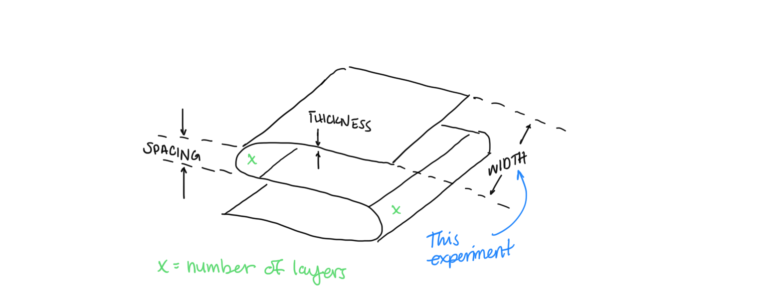
There are two printed spring designs that I want to test. I’ll call one the “ribbon spring” and the other “stacked ellipse.” For now I’ve only looked at the ribbon spring, mainly because there are slightly fewer parametric variables.
Spring Parameters
Lever arm spacing / radius of curves
Thickness of ribbon
Width of spring
Filament type (PLA, PETG, etc)
Filament brand
The Experiment
For this first round of testing, the experiment was only looking at the width of the spring. I printed 5 springs, all with the same configuration, except varying the width from 10 mm to 60 mm. I added the test mass in 7 steps, first noting the unloaded spring length. The ballast box itself was considered the first step, and was weighed by itself, along with the ball bearings, before being assembled. Then I added the fishing lead in a roughly even pattern. For each step, I noted the spring displacement and the mass reading from the kitchen scale.
The Results
At first glance, I didn’t expect the width to have a significant impact on the overall stiffness of the spring. However, if we consider each horizontal portion as a cantilevered beam we can look at some simple statics equations.
k = (3EI/l^3) where I is the second moment of inertia about the neutral axis. For a rectangle, I can be found with I = bh^3 / 12, where h is the height and b is the width. Substituting, we get the following
k = Ebh^3 / (4l^3)
Assuming that, E, h, and l are constant, we would hypothesize that the stiffness k is a linear function as we’re only varying b. Unfortunately, that’s not what we see.

The widest spring appears to be the stiffest

Here we see a highly non-linear relationship, when considering the stiffness as a function of width. R^2 = 0.986
Conclusions
Well, this was a fun design problem to come up with the test stand and there were some surprising results! There are clearly some other effects going on that make the approximation of each layer as a cantilevered beam an incorrect one. The first effect that stands out the most to me is that the curved section is also being distorted and will have some characteristic stiffness of it’s own.
Given the observation regarding the possible effect of the curved portion, I think I will pick a single width and vary the radius of the curved portion. Though, to effectively do this test, I should really control for the effects of the overall height of the spring and even more fundamentally, I should really print several specimens of the same design and get an idea for the variation just due to the 3D printing process.